Patterns
Patterns determine how material is distributed within a print. Different patterns can affect strength, flexibility and print speed using the same density setting.
The infill pattern also impacts the uniformity of the layer times, since the patterns may be constant, or present significant variations between adjacent layers.
There is no one-size-fits-all solution, as the best pattern depends on the specific print and its requirements.
Many patterns may look similar and have similar overall specifications, but they can behave very differently in practice.
As most settings in 3D printing, experience is the best way to determine which pattern works best for your specific needs.
Tip
Quickly compare patterns with the Patterns Quick Reference Table.
Analysis parameters
Strength
- X-Y Direction: The strength of the print in the "Horizontal" X-Y plane. Affected by the pattern's connections between walls, contact between layers, and path.
- Z Direction: The strength of the print in the "Vertical" Z direction. Affected by contact between layers.
Material Usage
Not all patterns use the same amount of material due to their Density Calculations and adjustments to the paths.
This leads to patterns that do not use the specified percentage but rather variations of it.
Print Time
Print time can vary significantly between patterns due to differences in their pathing and infill strategies.
Some patterns may complete faster due to more efficient use of the print head's movement, while others may take longer due to more complex paths.
Note
OrcaSlicer Time estimations are not always accurate, especially with complex patterns.
This analysis was estimated with Klipper Estimator.
Layer Time Variability
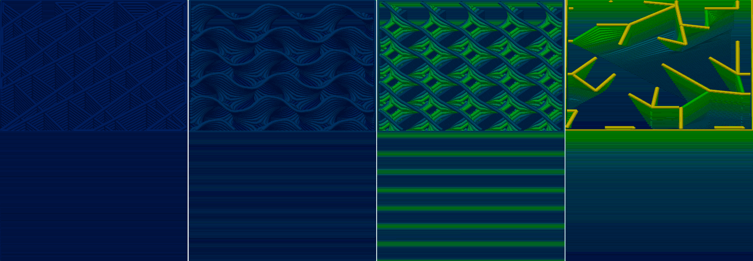
Layer time variability refers to the differences in time it takes to print each layer of a pattern. Some patterns may have consistent layer times, while others may experience significant fluctuations. These variations can potentially impact the outer appearance of the print due to differences in cooling and material flow between layers.
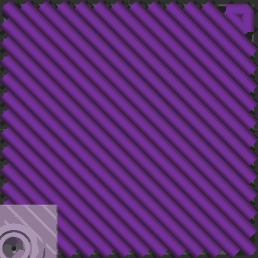
Monotonic
Rectilinear in a uniform direction for a smoother visual surface.
- Strength
- Horizontal (X-Y): Normal

- Vertical (Z): Normal
- Horizontal (X-Y): Normal
- Density Calculation: % of total infill volume
- Material Usage: Normal

- Print Time: Normal-Low

- Material/Time (Higher better): Normal-High

- Layer time Variability: None
- Material/Time (Higher better): Normal-High
- Material Usage: Normal
- Extra:
- Multiline: N/A
- Symmetric infill Y axis: N/A
- Smooth Factor: N/A
- Applies to:
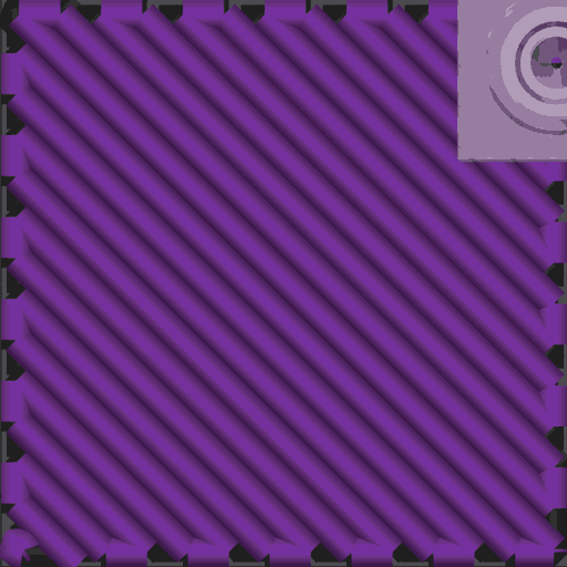
Monotonic line
Monotonic but avoids overlapping with the perimeter, reducing excess material at joints. May introduce visible seams and increase print time.
- Strength
- Horizontal (X-Y): Normal
- Vertical (Z): Normal
- Horizontal (X-Y): Normal
- Density Calculation: % of total infill volume
- Material Usage: Normal
- Print Time: Normal-Low
- Material/Time (Higher better): Normal-High
- Layer time Variability: None
- Material/Time (Higher better): Normal-High
- Material Usage: Normal
- Extra:
- Multiline: N/A
- Symmetric infill Y axis: N/A
- Smooth Factor: N/A
- Applies to:
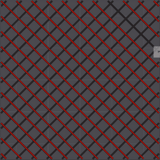
Rectilinear
Parallel lines spaced according to infill density. Each layer is printed perpendicular to the previous, resulting in low vertical bonding. Consider using new Zig Zag infill instead.
- Strength
- Horizontal (X-Y): Normal-Low

- Vertical (Z): Low

- Horizontal (X-Y): Normal-Low
- Density Calculation: % of total infill volume
- Material Usage: Normal
- Print Time: Normal-Low
- Material/Time (Higher better): Normal-High
- Layer time Variability: Unnoticeable
- Material/Time (Higher better): Normal-High
- Material Usage: Normal
- Extra:
- Applies to:
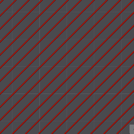
Aligned Rectilinear
Parallel lines spaced by the infill spacing, each layer printed in the same direction as the previous layer. Good horizontal strength perpendicular to the lines, but terrible in parallel direction. Recommended with layer anchoring to improve not perpendicular strength.
- Strength
- Horizontal (X-Y): Normal-Low
- Vertical (Z): Normal
- Horizontal (X-Y): Normal-Low
- Density Calculation: % of total infill volume
- Material Usage: Normal
- Print Time: Normal-Low
- Material/Time (Higher better): Normal-High
- Layer time Variability: Unnoticeable
- Material/Time (Higher better): Normal-High
- Material Usage: Normal
- Extra:
- Applies to:
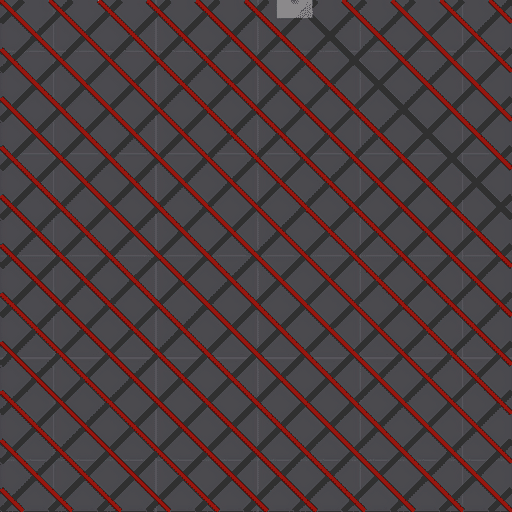
Zig Zag
Similar to rectilinear with consistent pattern between layers.
- Strength
- Horizontal (X-Y): Normal-Low
- Vertical (Z): Low
- Horizontal (X-Y): Normal-Low
- Density Calculation: % of total infill volume
- Material Usage: Normal
- Print Time: Normal-Low
- Material/Time (Higher better): Normal-High
- Layer time Variability: Unnoticeable
- Material/Time (Higher better): Normal-High
- Material Usage: Normal
- Extra:
- Multiline: No
- Symmetric infill Y axis: Yes
- Smooth Factor: No
- Applies to:
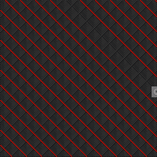
Cross Zag
Similar to Zig Zag but displacing each layer with Infill shift step parameter.
- Strength
- Horizontal (X-Y): Normal
- Vertical (Z): Low
- Horizontal (X-Y): Normal
- Density Calculation: % of total infill volume
- Material Usage: Normal
- Print Time: Normal-Low
- Material/Time (Higher better): Normal-High
- Layer time Variability: Unnoticeable
- Material/Time (Higher better): Normal-High
- Material Usage: Normal
- Extra:
- Multiline: No
- Symmetric infill Y axis: Yes
- Smooth Factor: No
- Applies to:
Locked Zag
Mode: Advanced.
Variables: skin_infill_density, skeleton_infill_density, infill_lock_depth, skin_infill_depth, skin_infill_line_width, skeleton_infill_line_width.
Type: skin_infill_density (Percentage), skeleton_infill_density (Percentage), infill_lock_depth (Float), skin_infill_depth (Float), skin_infill_line_width (Float or Percentage), skeleton_infill_line_width (Float or Percentage).
CLI Example: --skin-infill-density=20% (skin_infill_density shown; other variables above follow their own type).
Version of Zig Zag that adds extra skin.
When using this fill, you can individually modify the density of the skeleton and skin, as well as the size of the skin and how much interconnection there is between the skin and the skeleton (a lock depth of 50% of the skin depth is recommended).
- Strength
- Horizontal (X-Y): Normal-Low
- Vertical (Z): Normal-Low
- Horizontal (X-Y): Normal-Low
- Density Calculation: Similar to Zig Zag.
Skin density * ( Infill Area - Skin Area + lock depth area) + ( Skin density * Skin area).
- Material Usage: Normal-High

- Print Time: Normal-High
- Material/Time (Higher better): Normal
- Layer time Variability: None
- Material/Time (Higher better): Normal
- Material Usage: Normal-High
- Extra:
- Multiline: No
- Symmetric infill Y axis: Yes
- Smooth Factor: No
- Applies to:
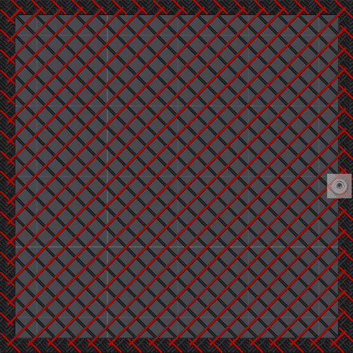
Line
Similar to rectilinear, but each line is slightly rotated to improve print speed.
- Strength
- Horizontal (X-Y): Low
- Vertical (Z): Low
- Horizontal (X-Y): Low
- Density Calculation: % of total infill volume
- Material Usage: Normal
- Print Time: Normal-Low
- Material/Time (Higher better): Normal-High
- Layer time Variability: None
- Material/Time (Higher better): Normal-High
- Material Usage: Normal
- Extra:
- Multiline: No
- Symmetric infill Y axis: No
- Smooth Factor: No
- Applies to:
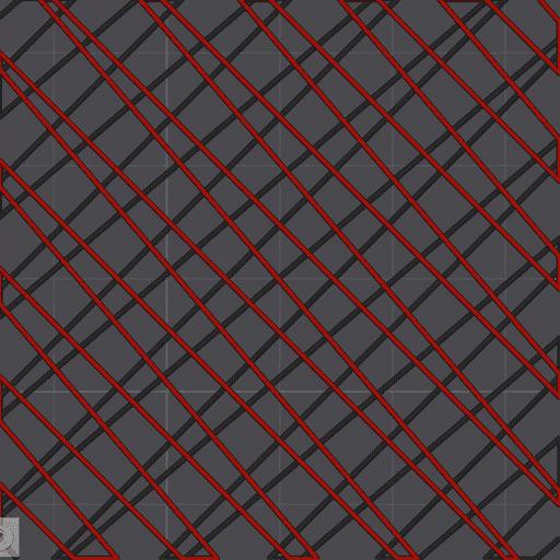
Grid
Two-layer pattern of perpendicular lines, forming a grid. Overlapping points may cause noise or artifacts.
- Strength
- Horizontal (X-Y): High

- Vertical (Z): High
- Horizontal (X-Y): High
- Density Calculation: % of total infill volume
- Material Usage: Normal
- Print Time: Low

- Material/Time (Higher better): Normal-High
- Layer time Variability: None
- Material/Time (Higher better): Normal-High
- Material Usage: Normal
- Extra:
- Applies to:
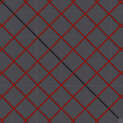
Triangles
Triangle-based grid, offering strong X-Y strength but with triple overlaps at intersections.
- Strength
- Horizontal (X-Y): High
- Vertical (Z): Normal
- Horizontal (X-Y): High
- Density Calculation: % of total infill volume
- Material Usage: Normal
- Print Time: Normal-Low
- Material/Time (Higher better): Normal-High
- Layer time Variability: None
- Material/Time (Higher better): Normal-High
- Material Usage: Normal
- Extra:
- Applies to:
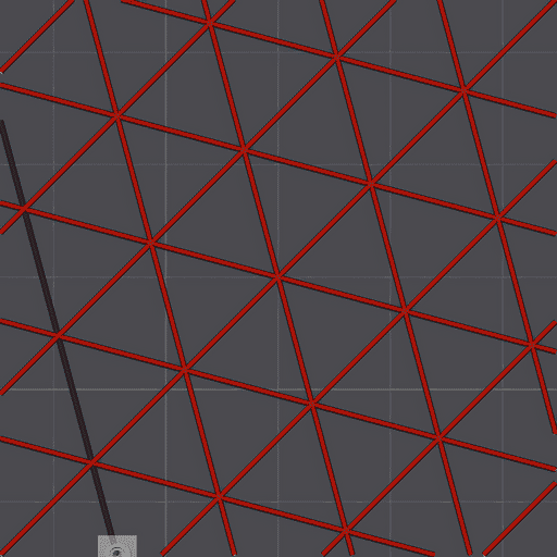
Tri-hexagon
Similar to the triangles pattern but offset to prevent triple overlaps at intersections. This design combines triangles and hexagons, providing excellent X-Y strength.
- Strength
- Horizontal (X-Y): High
- Vertical (Z): Normal-High
- Horizontal (X-Y): High
- Density Calculation: % of total infill volume
- Material Usage: Normal
- Print Time: Normal-Low
- Material/Time (Higher better): Normal-High
- Layer time Variability: None
- Material/Time (Higher better): Normal-High
- Material Usage: Normal
- Extra:
- Applies to:
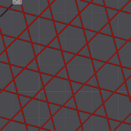
Cubic
3D cube pattern with corners facing down, distributing force in all directions. Triangles in the horizontal plane provide good X-Y strength.
- Strength
- Horizontal (X-Y): High
- Vertical (Z): High
- Horizontal (X-Y): High
- Density Calculation: % of total infill volume
- Material Usage: Normal
- Print Time: Normal-Low
- Material/Time (Higher better): Normal-High
- Layer time Variability: Unnoticeable
- Material/Time (Higher better): Normal-High
- Material Usage: Normal
- Extra:
- Applies to:
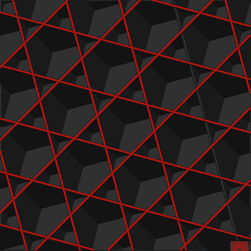
Adaptive Cubic
Cubic pattern with adaptive density: denser near walls, sparser in the center. Saves material and time while maintaining strength, ideal for large prints.
- Strength
- Horizontal (X-Y): Normal-High
- Vertical (Z): Normal-High
- Horizontal (X-Y): Normal-High
- Density Calculation: Same as Cubic but reduced in the center
- Material Usage: Low
- Print Time: Low
- Material/Time (Higher better): Normal
- Layer time Variability: Unnoticeable
- Material/Time (Higher better): Normal
- Material Usage: Low
- Extra:
- Applies to:
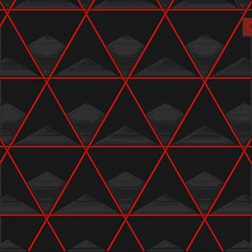
Quarter Cubic
Cubic pattern with extra internal divisions, improving X-Y strength.
- Strength
- Horizontal (X-Y): High
- Vertical (Z): High
- Horizontal (X-Y): High
- Density Calculation: % of total infill volume
- Material Usage: Normal
- Print Time: Normal-Low
- Material/Time (Higher better): Normal-High
- Layer time Variability: Unnoticeable
- Material/Time (Higher better): Normal-High
- Material Usage: Normal
- Extra:
- Applies to:
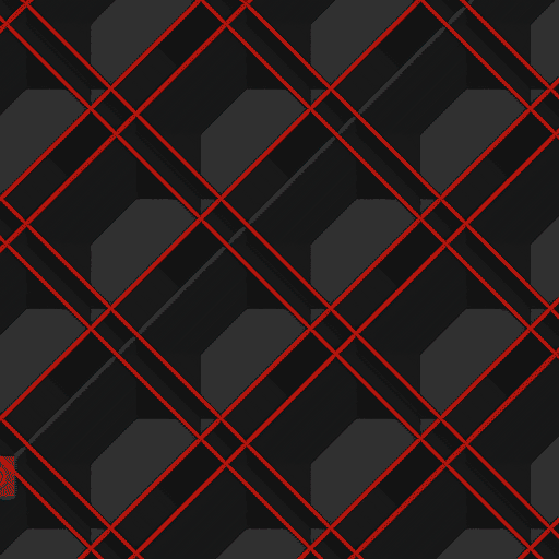
Support Cubic
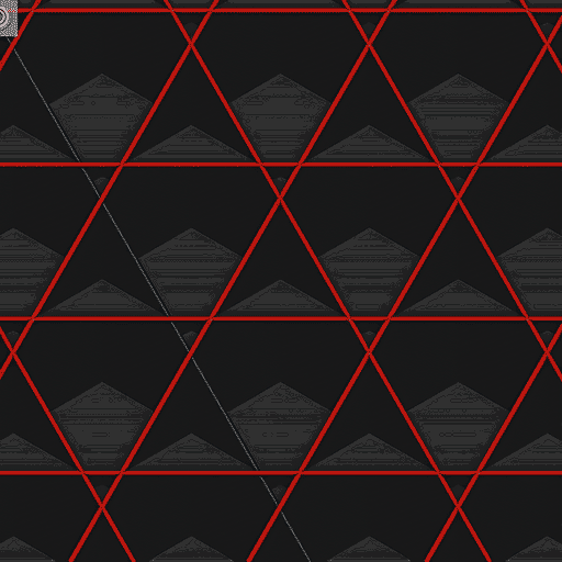
Support |Cubic is a variation of the Cubic infill pattern that is specifically designed for support top layers. Will use more material than Lightning infill but will provide better strength. Nevertheless, it is still a low-density infill pattern.
- Strength
- Horizontal (X-Y): Low
- Vertical (Z): Low
- Horizontal (X-Y): Low
- Density Calculation: % of layer before top shell layers
- Material Usage: Extra-Low

- Print Time: Extra-Low
- Material/Time (Higher better): Low
- Layer time Variability: Likely Noticeable
- Material/Time (Higher better): Low
- Material Usage: Extra-Low
- Extra:
- Applies to:
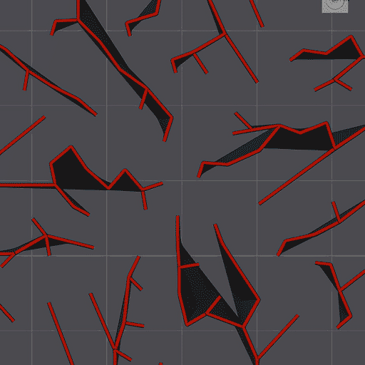
Lightning
Mode: Expert.
Variables: lightning_overhang_angle, lightning_prune_angle, lightning_straightening_angle.
Type: Float.
CLI Example: --lightning-overhang-angle=1 (same pattern for the other variables above).
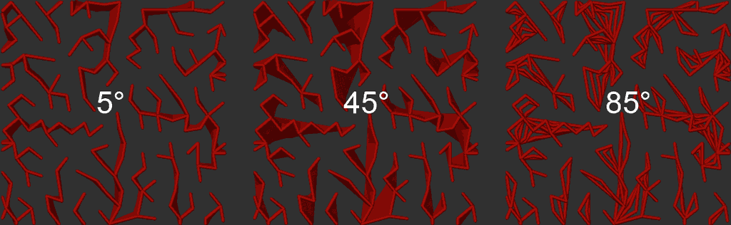
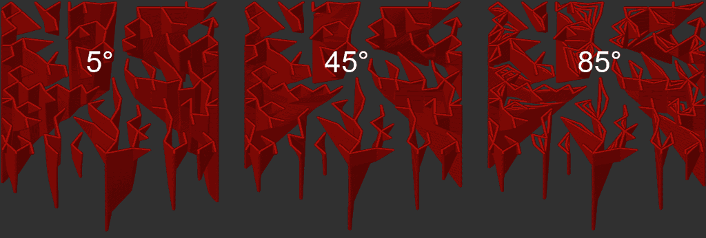
Ultra-fast, ultra-low material infill. Designed for speed and efficiency, ideal for quick prints or non-structural prototypes.
Overhang Angle
Similar to the overhang angle used for support generation, but specifically for Lightning infill.
It determines how far the infill can extend from walls before needing support.
Prune Angle
Controls how aggressively short/unsupported branches of the Lightning infill are pruned.
A lower angle will result in more pruning, while a higher angle will allow for more unsupported branches.
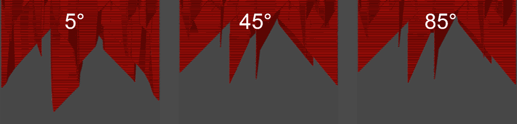
Straightening Angle
Limits how far junctions in the Lightning infill can be moved to straighten lines.
Using a low value will result in a low lateral distortion between layers, but may cause more pruning.
A higher value will allow for more straightening, improving strength but increasing lateral distortion.
- Strength
- Horizontal (X-Y): Low
- Vertical (Z): Low
- Horizontal (X-Y): Low
- Density Calculation: % of layer before top shell layers
- Material Usage: Ultra-Low

- Print Time: Ultra-Low
- Material/Time (Higher better): Normal-Low
- Layer time Variability: Likely Noticeable
- Material/Time (Higher better): Normal-Low
- Material Usage: Ultra-Low
- Extra:
- Multiline: Classic
- Symmetric infill Y axis: No
- Smooth Factor: Yes
- Applies to:
Honeycomb
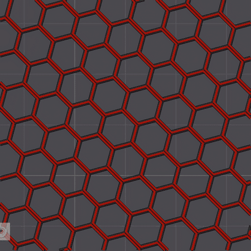
Hexagonal pattern balancing strength and material use. Double walls in each hexagon increase material consumption.
- Strength
- Horizontal (X-Y): High
- Vertical (Z): High
- Horizontal (X-Y): High
- Density Calculation: % of total infill volume
- Material Usage: High

- Print Time: Ultra-High

- Material/Time (Higher better): Low
- Layer time Variability: None
- Material/Time (Higher better): Low
- Material Usage: High
- Extra:
- Applies to:
3D Honeycomb
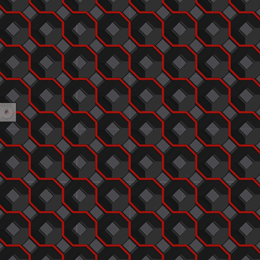
This infill tries to generate a printable honeycomb structure by printing squares and octagons maintaining a vertical angle high enough to maintain contact with the previous layer.
Fill pattern tops
Mode: Advanced.
Variable: infill_complete_top.
Type: Boolean.
CLI Example: --infill-complete-top=1.
Important
NEW FEATURE: Fill pattern tops
Available in: Nightly builds or Releases greater than 2.4.2.
The square at the top of each cell is left open by default. This option covers those squares.
Whenever the pattern changes its print direction, extra lines are bridged across the squares of the previous layer. This is added on top of the normal pattern, which keeps its structural stability.
- Disabled (default): the squares are left open.
- Enabled: the squares are covered.
The option is only shown when the Sparse infill pattern is 3D Honeycomb and the Sparse infill density is above 0%.
Useful for:
- Functional parts, for example keeping two channels (air and water) separate.
- Artistic prints where the upper surface of the pattern should be filled in.
Note
It is disabled by default because the direction reversals and non-extrusion moves needed to cover the squares substantially slow down the print.
Behavior with other settings:
- Fill Multiline: the cover is not multiplied by the number of lines. It is printed as a single zigzag pass, built up over as many layers as there are lines and changing direction on every layer.
- Density: the squares get smaller as the density increases (and larger with more Fill Multiline lines). When a square is too small to fit a cover line, none is generated, so the option has no effect at high densities.
- Line spacing: the cover lines are intentionally closer together than the line width, so the squares close without gaps.
Note
The covers are bridges, and small pinholes can remain in them. Test your print if it must be airtight or watertight.
- Strength
- Horizontal (X-Y): Normal-High
- Vertical (Z): Normal-High
- Horizontal (X-Y): Normal-High
- Density Calculation: Unknown
- Material Usage: Normal-Low
- Print Time: Extra-High

- Material/Time (Higher better): Low
- Layer time Variability: Possibly Noticeable
- Material/Time (Higher better): Low
- Material Usage: Normal-Low
- Extra:
- Multiline: Classic
- Symmetric infill Y axis: No
- Smooth Factor: Yes
- Applies to:
Lateral Honeycomb
Mode: Advanced.
Variable: infill_overhang_angle.
Type: Float.
CLI Example: --infill-overhang-angle=1.
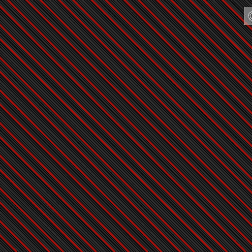
Vertical Honeycomb pattern. Acceptable torsional stiffness. Developed for low densities structures like wings. Improve over Lateral Lattice offers same performance with lower densities.This infill includes a Overhang angle parameter to improve the point of contact between layers and reduce the risk of delamination.
- Strength
- Horizontal (X-Y): Normal-Low
- Vertical (Z): Normal-Low
- Horizontal (X-Y): Normal-Low
- Density Calculation: % of total infill volume
- Material Usage: Normal
- Print Time: Normal-Low
- Material/Time (Higher better): Normal-High
- Layer time Variability: Possibly Noticeable
- Material/Time (Higher better): Normal-High
- Material Usage: Normal
- Extra:
- Applies to:
Lateral Lattice
Mode: Advanced.
Variables: lateral_lattice_angle_1, lateral_lattice_angle_2.
Type: Float.
CLI Example: --lateral-lattice-angle-1=1 (same pattern for the other variables above).
Low-strength pattern with good flexibility. You can adjust Angle 1 and Angle 2 to optimize the infill for your specific model. Each angle adjusts the plane of each layer generated by the pattern. 0° is vertical.
- Strength
- Horizontal (X-Y): Normal-Low
- Vertical (Z): Low
- Horizontal (X-Y): Normal-Low
- Density Calculation: % of total infill volume
- Material Usage: Normal
- Print Time: Normal-Low
- Material/Time (Higher better): Normal-High
- Layer time Variability: Unnoticeable
- Material/Time (Higher better): Normal-High
- Material Usage: Normal
- Extra:
- Applies to:
Cross Hatch
Mode: Advanced.
Variable: infill_shift_step.
Type: Float.
CLI Example: --infill-shift-step=1.
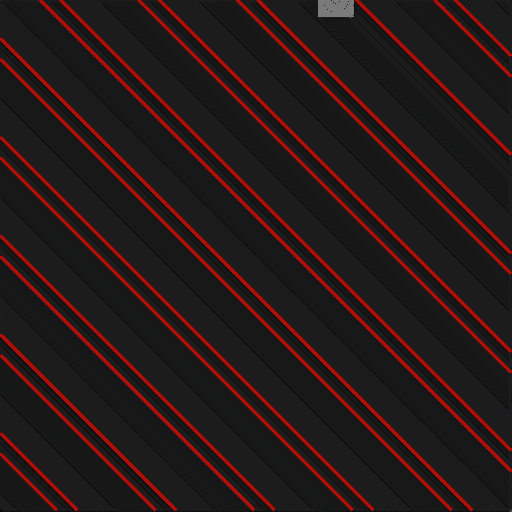
Similar to Gyroid but with linear patterns, creating weak points at internal corners.
Easier to slice but consider using TPMS-D or Gyroid for better strength and flexibility.
- Strength
- Horizontal (X-Y): Normal-High
- Vertical (Z): Normal-High
- Horizontal (X-Y): Normal-High
- Density Calculation: % of total infill volume
- Material Usage: Normal
- Print Time: High
- Material/Time (Higher better): Low
- Layer time Variability: Likely Noticeable
- Material/Time (Higher better): Low
- Material Usage: Normal
- Extra:
- Multiline: Classic
- Symmetric infill Y axis: No
- Smooth Factor: Yes
- Applies to:
TPMS-D
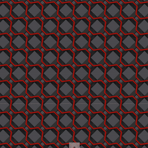
Triply Periodic Minimal Surface (Schwarz Diamond). Hybrid between Cross Hatch and Gyroid, combining rigidity and smooth transitions. Isotropic and strong in all directions. This geometry is faster to slice than Gyroid, but slower than Cross Hatch.
- Strength
- Horizontal (X-Y): High
- Vertical (Z): High
- Horizontal (X-Y): High
- Density Calculation: % of total infill volume
- Material Usage: Normal
- Print Time: High
- Material/Time (Higher better): Low
- Layer time Variability: Possibly Noticeable
- Material/Time (Higher better): Low
- Material Usage: Normal
- Extra:
- Multiline: Classic
- Symmetric infill Y axis: No
- Smooth Factor: No
- Adaptive Density: Yes
- Applies to:
TPMS-FK
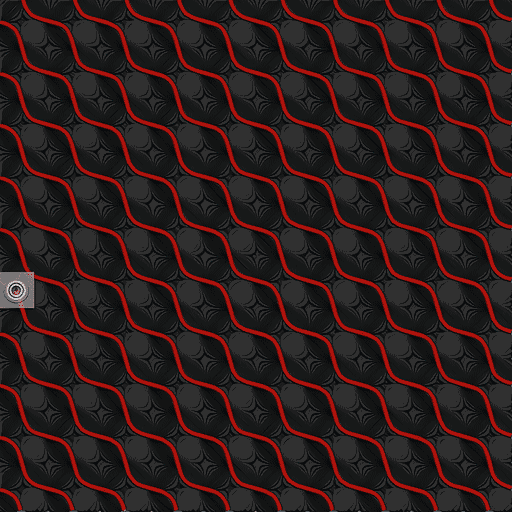
Triply Periodic Minimal Surface (Fischer–Koch S) pattern. Its smooth, continuous geometry resembles trabecular bone microstructure, offering a balance between rigidity and energy absorption. Compared to TPMS-D, it has more complex curvature, which can improve load distribution and shock absorption in functional parts.
- Strength
- Horizontal (X-Y): Normal-High
- Vertical (Z): Normal-High
- Horizontal (X-Y): Normal-High
- Density Calculation: % of total infill volume
- Material Usage: Normal
- Print Time: Ultra-High
- Material/Time (Higher better): Low
- Layer time Variability: Possibly Noticeable
- Material/Time (Higher better): Low
- Material Usage: Normal
- Extra:
- Multiline: Classic
- Symmetric infill Y axis: No
- Smooth Factor: No
- Adaptive Density: Yes
- Applies to:
Adaptive TPMS
Important
NEW FEATURE: Adaptive TPMS density Available in: Nightly builds or Releases greater than 2.4.2.
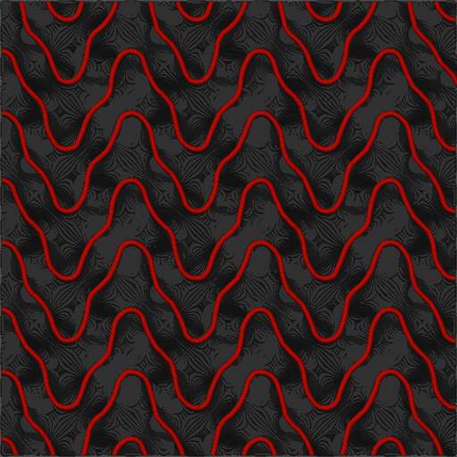
Gyroid, TPMS-D and TPMS-FK can grade their density inside the object: fine cells next to the walls and the top and bottom surfaces, where the infill supports the shells, growing continuously towards the center of the object, where they save material and print time.
Adaptive Density
Mode: Advanced.
Variable: tpms_adaptive.
Type: Choice.
Options: disabled, distance_warp, smooth_blend, stepped_shells, lobes, normal_z, normal_y, normal_x.
CLI Example: --tpms-adaptive=lobes.
Grades the Gyroid and TPMS infill inside the object: its cells grow from the surface of the object towards its center. The Sparse infill density is used at the surface and the Interior Density at the center.
| Mode | Follows | Use it for |
|---|---|---|
| Disabled | Nothing: the regular pattern at the sparse infill density. | |
| Distance warp | The distance to the nearest surface, with one continuous pattern warped around the lobe centers. | A smooth, connected concentric grading; the pattern is sheared in plates and long parts, and long parts are graded partly along their length. |
| Smooth blend | The distance to the nearest surface, with the patterns of neighbouring densities blended into each other. | A concentric grading without steps; small loops where the densities blend. |
| Stepped shells | The distance to the nearest surface, including the top and bottom, like concentric shells: each shell gets the regular pattern at its density, about 1.5 times apart, with its lines joined along the shell. | A concentric grading with an undistorted pattern; the density changes in steps. |
| Lobes | The whole 3D shape of the object, including its top and bottom: every lobe, a part joined to the rest by a narrower neck, towards its own center. | Most objects. |
| Normal Z | Each section of the object normal to Z, so the density does not change with the height. | Profiles extruded along Z, like tall prisms and tubes. |
| Normal Y, Normal X | Each section of the object normal to that axis, so the density does not change along it. | Profiles extruded along X or Y, like beams and bars lying on the bed. |
- The object is measured from its slices, so holes, negative parts and the union of overlapping parts are taken into account.
- Every separate body of the object, and every lobe of a body joined to the rest by a neck, like two united spheres, is graded towards its own center, its deepest point. The neck between two lobes is graded half way. With Lobes, the center of a tall object is at its middle height, so the infill is sparsest there and not along its whole height.
- The lines stay continuous: the pattern is scaled around the center, with round cells at the center and cells flattened along the surface near it.
- The parts that the center cannot reach in a straight line, like the far side of the hole of a ring, keep the sparse infill density.
- In Distance warp, Smooth blend and Stepped shells the interior density is at the point farthest from the surface, so a tall object keeps its whole core sparse and a plate is graded through its thickness. On spheres and cubes, Distance warp is the same as Lobes.
- Smooth blend and Stepped shells print more lines than their target where their densities meet, along the shells or where the patterns blend, so they save less material than Lobes for the same densities.
- In the Normal modes every section is graded the same way within its own outline. Along the axis, the cells keep the interior density, so near the surface they are stretched along the axis. With Normal X or Y, the layers next to the sides stay at the sparse infill density.
- The Gyroid Z-buckling bias optimization does not apply to adaptive infill.
- At a Sparse infill density of 100% the sparse infill is printed solid, so the adaptive options are hidden.
- Objects made only of parts thinner than the field grid cells (0.5 mm, up to a few mm for very large objects) use the regular pattern.
Interior Density
Mode: Advanced.
Variable: tpms_interior_density.
Type: Percentage.
CLI Example: --tpms-interior-density=20%.
Density of the adaptive infill at the center of the object.
It can also be higher than the sparse infill density, to make the core denser than the surface.
Adaptive Gradient
Mode: Advanced.
Variable: tpms_adaptive_gradient.
Type: Choice.
Options: linear, quadratic, exponential.
CLI Example: --tpms-adaptive-gradient=linear.
How the density changes from the surface (depth 0) to the center of the object (depth 1), where S is the sparse infill density and I the interior density:
| Gradient | Density at depth t |
Behavior |
|---|---|---|
| Linear | S + (I - S) × t |
Changes at a constant rate. |
| Quadratic | S + (I - S) × t² |
Stays close to the sparse infill density near the surface and changes faster towards the center. Uses the most material when the surface is denser. |
| Exponential | S × (I / S)ᵗ |
Changes quickly just below the surface and levels off towards the center. Uses the least material when the surface is denser. |
Gyroid
Mathematical, isotropic surface providing equal strength in all directions. Excellent for strong, flexible prints and resin filling due to its interconnected structure. Since it does not contain straight lines over long stretches, it helps reduce warping, as the material's contraction is distributed along its curved lines. This pattern may require more time to slice because of all the points needed to generate each curve. If your model has complex geometry, consider using a simpler infill pattern like TPMS-D or Cross Hatch.
Gyroid Optimized
Variable: gyroid_optimized.
Type: Boolean.
CLI Example: --gyroid-optimized=1.
Tightens the gyroid wave along the Z (vertical) axis at low infill density to shorten the effective vertical column length and improve Z-axis compression buckling resistance. Filament use is preserved. No effect at ~30% sparse infill density and above. Only applies when Sparse infill pattern is set to Gyroid.
- Strength
- Horizontal (X-Y): High
- Vertical (Z): High
- Horizontal (X-Y): High
- Density Calculation: % of total infill volume
- Material Usage: Normal
- Print Time: Ultra-High
- Material/Time (Higher better): Low
- Layer time Variability: Unnoticeable
- Material/Time (Higher better): Low
- Material Usage: Normal
- Extra:
- Multiline: Classic
- Symmetric infill Y axis: No
- Smooth Factor: No
- Adaptive Density: Yes
- Applies to:
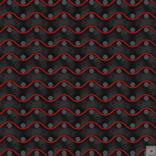
Concentric
Fills the area with progressively smaller versions of the outer contour, creating a concentric pattern. Ideal for 100% infill or flexible prints.
- Strength
- Horizontal (X-Y): Low
- Vertical (Z): Normal
- Horizontal (X-Y): Low
- Density Calculation: % of total infill volume
- Material Usage: Normal
- Print Time: Normal-Low
- Material/Time (Higher better): Normal-High
- Layer time Variability: None
- Material/Time (Higher better): Normal-High
- Material Usage: Normal
- Extra:
- Multiline: Classic
- Symmetric infill Y axis: No
- Smooth Factor: Yes
- Applies to:
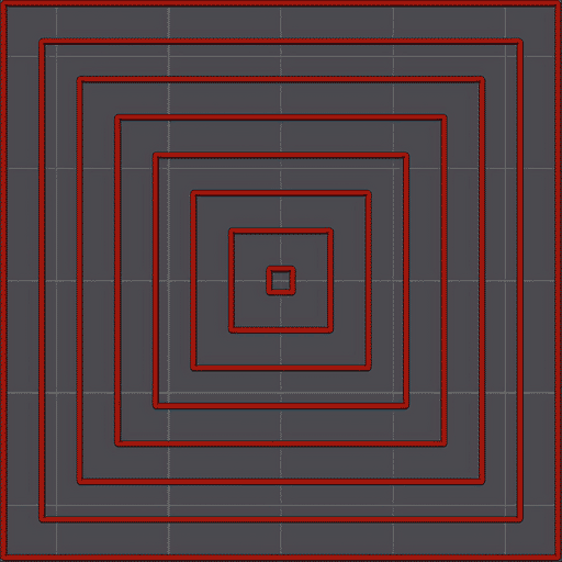
Hilbert Curve
Hilbert Curve is a space-filling curve that can be used to create a continuous infill pattern. It is known for its aesthetic appeal and ability to fill space efficiently. Print speed is very low due to the complexity of the path, which can lead to longer print times. It is not recommended for structural parts but can be used for aesthetic purposes.
- Strength
- Horizontal (X-Y): Low
- Vertical (Z): Normal
- Horizontal (X-Y): Low
- Density Calculation: % of total infill volume
- Material Usage: Normal
- Print Time: Extra-High
- Material/Time (Higher better): Low
- Layer time Variability: None
- Material/Time (Higher better): Low
- Material Usage: Normal
- Extra:
- Multiline: Classic
- Symmetric infill Y axis: No
- Smooth Factor: Yes
- Applies to:
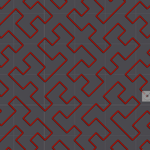
Archimedean Chords
Spiral pattern that fills the area with concentric arcs, creating a smooth and continuous infill. Can be filled with resin thanks to its interconnected hollow structure, which allows the resin to flow through it and cure properly.
- Strength
- Horizontal (X-Y): Low
- Vertical (Z): Normal
- Horizontal (X-Y): Low
- Density Calculation: % of total infill volume
- Material Usage: Normal
- Print Time: Normal-Low
- Material/Time (Higher better): Normal-High
- Layer time Variability: None
- Material/Time (Higher better): Normal-High
- Material Usage: Normal
- Extra:
- Applies to:
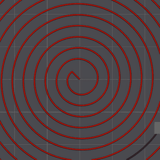
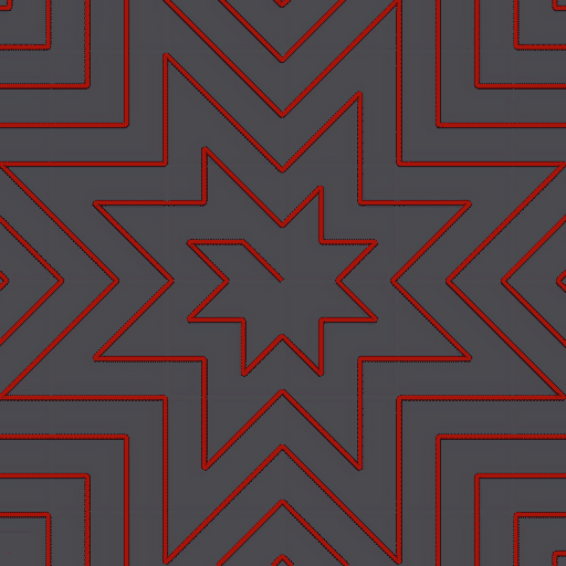
Octagram Spiral
Aesthetic pattern with low strength and high print time.
- Strength
- Horizontal (X-Y): Low
- Vertical (Z): Normal
- Horizontal (X-Y): Low
- Density Calculation: % of total infill volume
- Material Usage: Normal
- Print Time: Normal
- Material/Time (Higher better): Normal
- Layer time Variability: None
- Material/Time (Higher better): Normal
- Material Usage: Normal
- Extra:
- Multiline: Classic
- Symmetric infill Y axis: No
- Smooth Factor: Yes
- Applies to: